Laser cutting process - carbon steel material
I. Cutting of Carbon Steel Materials
1.1 Perforation Types and Cutting Principles
Phenomenon:
Perforation types mainly include pulse processing and continuous wave (CW) processing (as shown in Figure 3.1-1). The perforation process begins with the laser beam irradiating and heating the surface of the material (1), then gradually deepens into the material (2)~(4), and finally completes the perforation (5) in a continuous and uninterrupted manner.
-
CW Conditions: When using CW conditions, the focal point should be set above the surface of the material (2 > 0) to enlarge the processing aperture. As the perforation deepens, the focal point gradually moves downward until the perforation is completed.
-
Pulse Conditions: When using pulse conditions, it helps to suppress heat input, thereby achieving the effect of small aperture processing.

[Principle]
-
Perforation Using Pulse Conditions
When the thickness of the carbon steel material exceeds 9mm, if perforation is performed under pulse conditions, the processing time will increase significantly. However, the diameter of the perforated hole will be only about 0.4mm, which is narrower than the cut seam, and the heat-affected zone will also be smaller. Figure 3.1-2 shows the morphology when the laser irradiation is stopped midway through the perforation, which is used to check the progress of the perforation.Pulse perforation is achieved by the repeated irradiation and stopping of the laser, which melts (or evaporates) the material, discharges the molten material, and cools it, thereby gradually deepening the perforation. If there is a timing discrepancy between the melting and the discharge processes, it can lead to molten metal spattering upward or prolonged perforation time. When the frequency is in the range of 100 to 200 Hz, the higher the peak power of the pulse is set, the better the quality of the perforated hole. If a higher frequency is used, only the melting capability increases, while the efficiency of molten metal discharge and cooling decreases.

- Perforation Using CW Conditions
When perforating under continuous wave (CW) conditions, a large amount of molten metal tends to spatter upward. If the molten metal cannot be discharged through the extremely small aperture above, overburning may occur. The downside of CW perforation is that a significant amount of molten metal splashes onto the surface of the workpiece, but the advantage is that it can greatly reduce processing time. Figure 3.1-3 shows photos of the surface and back of SS400 material with a thickness of 12mm after perforation using CW output with different nozzle diameters. The nozzle diameter corresponds to the range of oxygen being sprayed onto the perforation area. The larger the nozzle diameter, the larger the diameter of the perforated hole.

- Others
Under normal conditions, the perforation conditions are adjusted while observing the perforation progress under either pulse conditions or CW conditions (or under both conditions). The ideal perforation effect is characterized by a small aperture and a short processing time.
1.2 Methods to Shorten Perforation Time
Phenomenon
The methods to shorten perforation time vary depending on the type of perforation.
- Pulse Condition Perforation
When using pulse conditions for perforation, the laser irradiation is pulsed. A good effect can only be achieved if the melting and evaporation during laser irradiation are well matched with the cooling during the pause. If the focus is solely on enhancing the melting and evaporation, it can easily cause overburn; conversely, if only the cooling effect is emphasized, the perforation time will become longer.
- CW Condition Perforation
CW perforation tends to cause an overburn phenomenon. The advantage of CW perforation is that it can shorten perforation time, but as the thickness of the plate increases, the melting range will continue to expand, thus affecting the processing quality.
- Adjusting Conditions Based on Perforation Progress
In perforation processing, when the amount of laser irradiation is either too high or too low, the conditions should be adjusted while observing the processing situation until the optimal conditions are achieved.
Causes and Countermeasures
- Pulse Mode Perforation
To enhance melting capacity and cooling capacity, it is necessary to irradiate a large amount of energy in a short time and ensure adequate cooling time after irradiation. As shown in Figures 3.2-1 and 3.2-2, the effect of pulse irradiation with a high peak rectangular pulse waveform is ideal. The energy required for melting is expressed as the product of intensity and irradiation time . Compared to triangular wave pulses, rectangular wave pulses require half the irradiation time to achieve the same energy, resulting in less heat input into the workpiece, thereby reducing the likelihood of overburn. Figure 3.2-3 shows the effect of pulse peak power and pulse average power on perforation in 6mm thick SS400 material, where higher pulse peak power results in shorter perforation time.


- CW Mode Perforation
When the plate thickness exceeds 12mm, it is advisable to select a nozzle with a smaller diameter. For thick plate cutting where cutting surface quality is prioritized, separate nozzles should be chosen for perforation and cutting.
- Adjusting Conditions Based on Perforation Progress
When adjusting conditions, the brightness of the molten state in the perforated part can be observed using sensors. If the molten range tends to expand, the laser intensity should be reduced; conversely, if the melting effect decreases, the laser intensity should be increased. This approach aims to achieve small-diameter, high-speed perforation.
1.3 Methods to Resolve Perforation Defects
Phenomenon
The main factors causing perforation defects include the moment of occurrence, the location of occurrence, the time of occurrence, and the material's intrinsic factors. Refer to Table 3.3-1 for an analysis of the key factors.
Causes and Countermeasures
-
Moment of Defect Occurrence
It is essential to determine when the defect occurs—whether it happens midway during the perforation process or right after the perforation when cutting begins. If the defect occurs midway, check whether it happens right at the start of the perforation or during the transition to other conditions, and adjust accordingly. If the defect occurs just before the perforation ends, it may be due to switching from perforation to cutting conditions before the hole is fully pierced. In this case, the perforation time needs to be extended. If the defect appears right at the start of cutting, it may be due to accumulated debris around the perforation area, making cutting unstable. In such cases, pulse conditions should be set at the beginning of the cut. -
Location of the Processing Defect
If perforation defects are concentrated in a specific area on the processing platform, it could be due to a misalignment between the laser and nozzle center, requiring adjustment.
When perforation positions are dense or located near the cutting line, the perforated area can easily be at a high temperature. Figure 3.3-1 shows the processing results at various temperatures when the material's temperature is raised from room temperature to 200°C, using 12mm thick SS400 material. The data shows the overburn rate based on 50 perforations at each temperature. It can be observed that processing defects increase with rising temperatures. To reduce processing defects, machining should be performed as much as possible in the cooled state of the material, and the processing route should be optimally designed.

3. Time of Defect Occurrence
If the processing defects increase as processing time progresses, observe whether increasing the cooling time can restore normal operation. If it does, this indicates that a thermal lens effect has occurred in the optical components, and maintenance of the optical components is required. However, if increasing the cooling time does not resolve the issue, it might be due to a malfunction in the oscillator, causing fluctuations in output power. In such cases, contact the after-sales service department.
4. Material Causing Processing Defects
When determining whether the defect originates from the material, first check if the material has been used before. If it has been used before, there is no need to adjust the processing conditions, as the defect is likely due to a malfunction in the processing machine or optical components.
Figure 3.3-2 shows the time required to penetrate 16mm thick SS400 material produced by various manufacturers during perforation. If the material quality changes, confirm the perforation time before continuous processing, or set a slightly longer overall processing time.

II. Methods to Solve Overburning During Cutting Process
2.1 Methods to Address Frequent Overburning When Processing 12mm Thick and 25mm Square Shapes
[Phenomenon]
When cutting carbon steel materials, if the shape being processed has sharp corners, the sharp corners are prone to melting or overburning. The cutting speed decreases as the material thickness increases, and the heat generated during cutting accumulates within the material, causing the material temperature to rise and resulting in frequent melting or overburning at the sharp corners.
[Reason]
As shown in Figure 3.4-1, in a good cutting process, the thermal energy produced by the laser and the thermal energy generated by oxidation combustion are effectively dissipated into the material being processed, which is also effectively cooled. If cooling is insufficient, overburning occurs. Sharp corners have a smaller volume and narrower heat dissipation area, so the temperature rises easily, leading to overburning. Additionally, during piercing, the laser absorbed by the inner wall of the hole causes the temperature to rise sharply in a very small space, which also easily leads to overburning.

[Solution]
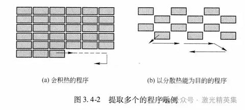
(1) When processing multiple small-sized shapes, heat will continue to accumulate as the process progresses, making overburning more likely to occur during the latter part of the processing. The solution, as shown in Figure 3.4-2, is to spread the processing paths as much as possible to avoid continuous movement in one direction. This allows the heat to dissipate more effectively. The processing paths should be optimized according to the actual shape being processed.
(2) As shown in Figure 3.4-3, if overburning is concentrated at the sharp corners, it can be effectively prevented by replacing the sharp corners with small radii (R) in the processing shape. The larger the radius R, the more effective the prevention. As the thickness of the material increases, the radius R also needs to be correspondingly increased.

(3) Sharp corners tend to experience melting as the temperature increases during processing because the processing area is already at high temperature when the laser beam passes through (as shown in Figure 3.4-4). If the advancement speed of the laser beam is faster than the rate of heat conduction, the cutting process can be completed before the material becomes overheated, effectively preventing melting.

Under typical conditions, the rate of heat conduction that causes melting is about 2m/min. If the cutting speed is greater than 2m/min, melting generally does not occur. This is also why sharp corners in carbon steel materials with a thickness of less than 6mm experience less melting. For carbon steel materials thicker than 9mm, achieving the same effect requires using a processing condition with an output power of over 4kW, necessitating a high-output power oscillator.
(4) If auxiliary gases such as nitrogen or air are used, oxidation combustion reactions will not occur, and thus melting or overburning will generally not happen.
2.2 Identifying the Causes of Overburning in 16mm Thick Plates: Workpiece Causes
[Phenomenon]
To identify the causes of overburning due to uncontrolled heat, the processing phenomena should be broken down by steps to find the underlying reasons in each step.
The laser cutting process flow is shown in Figure 3.5-1:
- The laser is directed at the surface of the material.
- The laser is absorbed, causing melting.
- The molten part burns due to the auxiliary gas's combustion support.
- The burning further expands in the direction of the material's thickness.
- The molten metal is expelled from the cut seam.
These processes repeat continuously until the cutting goal is achieved.

The causes of overburning can be attributed to issues with the processing machine or the workpiece. Specifically:
- Machine-related causes manifest in steps ① and ③.
- Workpiece-related causes manifest in steps ②, ④, and ⑤.
[Causes and Countermeasures]
-
Causes Related to Laser Absorption
Instability in laser cutting process ② can lead to overburning. If the material's surface oxidation layer (scale) is poorly adhered or uneven, the material's absorption of the laser will be inconsistent, resulting in unstable heat generation. Figure 3.5-2 shows a comparison of cutting surfaces when the laser is applied to the top and bottom of the same material. It demonstrates that the state of the material's surface oxidation layer affects cutting surface quality. When placing the material, carefully check the surface condition and position the side with the better oxidation layer facing up.

For materials where the top and bottom surfaces cannot be arbitrarily set, a secondary cutting method can be used. This involves first using the laser energy to even out the uneven surface of the material before proceeding with the main cutting. Specifically, you would:
-
Initial Surface Treatment: Reduce the laser's energy density to just the level required to melt the material's surface. Melt the surface along the cutting path, ensuring that the melted width is slightly wider than the cut seam.
-
Main Cutting: Switch to the standard cutting conditions to complete the cutting process.
Figure 3.5-3 compares samples cut using the single-cutting method and the secondary cutting method. It shows that the cutting surface quality achieved with the secondary cutting method is essentially equivalent to that of materials with a well-maintained surface.

2. Causes Related to Combustion in the Thickness Direction or Ejection of Molten Metal
This cause leads to instability in laser cutting processes ④ and ⑤. Variations in the internal composition of the material can affect the combustion reaction heat or the flow state of the molten metal. Materials manufactured by domestic Japanese suppliers generally show little difference in processing performance. However, materials from overseas suppliers can exhibit significant variations in processing performance. Figure 3.5-4 shows a comparison of cutting 16mm thick carbon steel under the same power output and cutting speed conditions. If using materials from overseas suppliers with higher Si or Mn content, special attention should be paid to the focus position and auxiliary gas pressure settings during the setup.

2.3 Identifying the Causes of Overburning in 16mm Thick Plates: Machine-Related Causes
[Causes and Countermeasures]
-
Auxiliary Gas Issues (Figure 3.6-1)
(1) Uneven Oxygen Flow: If oxygen is not uniformly directed around the molten metal, the combustion efficiency and flow of the molten metal will be uneven, leading to overburning due to varying cutting directions. Issues like laser beam misalignment, nozzle deformations, or slag build-up can disturb the auxiliary gas flow. The nozzle condition should be checked first.
(2) Low Gas Purity: If all the cutting surfaces are of poor quality, it may be due to low gas purity in the oxygen tank, resulting in rough and slagged lower parts of the cut surface. As the material thickness increases, the impact of auxiliary gas purity on processing quality becomes more significant. When diagnosing this issue, use a gas tank that has been previously confirmed to be accurate.

2. Laser Issues (Figure 3.6-2)
(1) Directional Issues During Cutting: If directional inconsistencies are observed during cutting, it is likely due to problems with the laser beam’s roundness or intensity distribution. The intensity of the laser directly affects its ability to melt metal. If there are issues with the beam’s roundness or intensity distribution, the combustion efficiency will vary with changes in cutting direction, leading to overburning. In this case, the shape of the beam mode needs to be checked.
(2) Overall Poor Cutting Surface Quality: This can be attributed to inadequate focusing of the lens. The temperature in the areas that need to be melted should be as high as possible, while the temperature in non-melting areas should be as low as possible. Variations in energy at these temperature boundaries can cause overburning. Inadequate focusing may be caused by abnormalities in the lens or PR mirrors, or issues with the optical path or reflecting mirrors.

3. Other Causes (Figure 3.6-3)
(1) Decreasing Quality Over Time: If the quality of the cut worsens as the process progresses, it could be due to heat accumulation in the material, causing a rise in material temperature and resulting in overburning. In such cases, the cutting path should be set to a dispersed route to prevent excessive concentration of heat.
(2) Quality Deterioration in the Later Stages of Long Cutting Paths: If the quality starts to deteriorate in the latter half of a longer cutting path, it may be due to contaminants on the lens or PR mirrors absorbing the laser and causing thermal lensing effects. Clean the lens or PR mirrors and other optical components. If cleaning does not resolve the issue, the optical components may need to be replaced.
(3) Defects in Specific Areas of the Cutting Platform: If defects occur in a specific area of the cutting platform, the cause may be misalignment in the optical path. This misalignment can cause the nozzle center to deviate from the laser center as the cutting position moves, leading to overburning. In this case, adjust the optical path alignment.


[Causes]
As shown in Figure 3.8-2, piercing involves directing a laser onto the material's surface and gradually removing the molten metal to create a hole. If the output power is set too high to accelerate the melting process, the small hole created during piercing may not be able to expel the molten metal quickly enough, causing heat to accumulate in the material. Additionally, as illustrated in Figure 3.8-3, when the hole diameter is within the range of 0.3 to 0.5mm, the hole walls are highly absorbent to the laser. This results in very high temperatures around the small hole, and with thicker plates, the depth of laser absorption into the hole's inner walls increases, causing even higher temperatures around the hole.

When piercing holes with a diameter of 0.3 to 0.5mm, the width of the cut seam is typically 0.5 to 0.8mm. Immediately starting the cutting process after piercing can lead to an increase in molten metal volume. In this case, the small hole may not be able to accommodate the rapidly expanding molten metal, resulting in a reverse ejection phenomenon.


3. Beam Mode and Processing Methods for Cutting Carbon Steel
3.1 Suitable Beam Mode for Cutting Thick Carbon Steel Plates
Phenomenon: In high-speed cutting of thin plates, a focused beam mode with high melting capability is more suitable. Typically, single-mode (TEM) beams focused through short focal length lenses are used in laser cutting. However, in thick plate cutting, simply increasing the melting capability is insufficient to effectively expel the molten metal from the kerf, and the margin for achieving high-quality cutting conditions is quite narrow. Figure 3.10-1 compares the margin for processing conditions when cutting 12mm thick carbon steel using single-mode (TEM) and multi-mode (TEM) beams. It shows that the processing condition margin is wider when using multi-mode beams.

Reason:
In the cutting of thick carbon steel plates, the beam mode plays a decisive role in determining the shape of the kerf. Figure 3.10-2 shows the two main factors related to the beam mode

1. Limiting the Range of Melting and Burning
The key to cutting thick plates is to ensure that the area that needs to be melted by laser irradiation reaches a high temperature, while the area that does not need to be melted remains as cool as possible. Especially at the starting point of the cut, the melting phenomenon on the surface of the workpiece is directly affected by the beam mode. At the point of laser irradiation, melting starts from the center, where the laser intensity is highest, and spreads outward, stopping where the energy density of the beam mode is low. The greater the inclination angle of the energy intensity distribution in the slope section of the beam mode, the less heat will be transferred to the area surrounding the kerf. Conversely, if the inclination angle is small, it will be difficult for the melting in the kerf to stop where it needs to, causing the burning range to expand, leading to uncontrolled heat and overburning. If the temperature at the boundary of the kerf width is too high, the burning will be difficult to stop at the kerf width boundary as it spreads from the center of the kerf outward, eventually resulting in overburning. Compared to a single beam mode, a multi-beam mode has a steeper gradient in the slope section, placing less load on the lens, making it more suitable for cutting thick plates.
2. Multiple Reflections within the Kerf
When the laser irradiates the workpiece, it undergoes multiple reflections within the kerf, facilitating the cutting process. The focal length of the lens affects the angle at which the laser irradiates the workpiece and the state of multiple reflections. The longer the focal length of the lens, the smaller the change in kerf width from top to bottom, which is advantageous for cutting thick plates. However, the longer the focal length of the lens, the smaller the inclination of the slope in the beam mode, requiring the focal length to be selected in conjunction with the beam mode.
3.2 Choosing the Most Suitable Nozzle for Cutting Thick Carbon Steel Plates
Phenomenon:
Cutting thick carbon steel plates primarily relies on an oxidation reaction, making the management of the purity of the auxiliary oxygen extremely important. This has already been discussed earlier. The purity of oxygen not only decreases at the beginning of the cutting process but also continues to decrease during the cutting process, leading to a decline in cutting quality and a reduction in cutting speed, which necessitates improvement.
Reason:
As shown in Figure 3.11-1, the auxiliary gas is sprayed from above the workpiece. When the airflow collides with the surface of the material, turbulence occurs. As the airflow enters the kerf, burning along the direction of the plate thickness and the mixing of air into the kerf will cause the gas purity to decrease from the center of the kerf downward. This effect is particularly pronounced as the plate thickness increases or the cutting speed increases. The lower part of the cutting front will lag behind in the cutting direction, and the drop in gas purity will greatly affect the processing.

Solution:
If a standard single-hole nozzle is used, the diameter of the nozzle can be increased to enhance the shielding effect of oxygen on the processing area. However, this approach has drawbacks, such as narrowing the controllable and adjustable range of airflow and gas pressure, making it easier for slag to infiltrate and dirty the lens.
Figure 3.11-2 shows the use of a dual-structure nozzle. Using a dual nozzle not only allows oxygen to shield the cutting area but also helps maintain the oxygen purity in the direction of the plate thickness. The oxygen emitted from the outer nozzle assists the combustion-supporting gas ejected from the central nozzle. However, adjusting the airflow characteristics is primarily done through the central nozzle.

The roles of the dual nozzle are as follows: The oxygen emitted from the central nozzle causes the burning to penetrate deeper from the surface of the material downward, with the gas purity decreasing during the burning process. The outer nozzle then supplements the gas where the purity has decreased. Additionally, as the cutting progresses, the auxiliary oxygen emitted from the outer nozzle helps to block external gases from infiltrating the kerf.
The thicker the material, the more the oxidation reaction in the lower part of the plate will lag behind. When the lower part of the cutting front falls behind the processing direction, it will move out of the range of the oxygen jet. Similarly, when the cutting speed is increased, the lower part of the cutting front will also lag behind the processing direction, moving out of the range of the oxygen jet. To address this lagging phenomenon in the lower part of the cutting front, a dual nozzle can effectively utilize the oxygen emitted from the dual nozzle to prevent air from infiltrating the processing area.
3.3 Methods to Prevent Melting Damage at the End of Thick Plate Cutting
Phenomenon:
In the cutting of thick carbon steel plates, it is common for melting damage to occur at the end of the cutting process. In processes like threading holes, depending on quality requirements, it may be necessary to repair the melted areas. This is especially true in cases where the material is thick and the hole diameter is small, where the amount of melting damage can be significant.
Reason:
As shown in Figure 3.12-1, the heat conduction at the processing site is faster than the cutting speed, causing heat to act ahead of the laser. When processing approaches the end section, the heat loses its conduction space, leaving the end part in a high-temperature state. If oxygen continues to be supplied at this point, it can cause overburning, leading to melting damage.

Solution:
Methods to prevent melting damage at the end of thick plate cutting include:
(1) Stop processing before melting damage occurs;
(2) Reduce heat input;
(3) Suppress the oxidation reaction;
(4) Process before the temperature rises;
(5) Compensation.
(1) Stop processing before melting damage occurs → Add micro-joints
Stop the cutting process just before completion, leaving a small portion uncut (micro-joints). The amount of micro-joints should be determined based on factors such as (i) the thickness of the material, (ii) the shape of the cut, (iii) the material type, and (iv) the kerf width (focus position, lens focal length).
(2) Reduce heat input → Switch to pulse conditions with lower heat input
Switch the conditions at the part prone to melting damage to pulse conditions with lower heat input. Setting parameters such as (i) low frequency, (ii) low duty cycle, (iii) low speed, and (iv) low gas pressure for the pulse conditions can effectively suppress heat input.
(3) Suppress the oxidation reaction → Use air or nitrogen
Although the oxidation reaction heat from oxygen can enhance cutting performance, it can also cause excessive heat accumulation at the end part. Switching the processing gas at the end part to air or nitrogen, though it may cause dross defects, can effectively suppress the generation of oxidation reaction heat.
(4) Process before the temperature rises → Increase processing speed
If there is room to increase the cutting speed by adjusting the output power, the cutting speed should be set to a level faster than the heat conduction speed. Specifically, the cutting speed should be set above 2 m/min.
(5) Compensation → Add a bulge program
In the program, add a bulge of the same amount as the melted portion. The bulge part will melt during processing, ultimately achieving balance in the processing and preventing melting damage.
3.4 Reasons and Solutions for the Difficulty of Cutting Rusty Materials
Phenomenon:
When cutting thick carbon steel plates, even materials that can usually be cut well may produce rough cut surfaces or experience overburning if there is rust on the surface. Figure 3.13-1 shows the cutting results for 12mm SS400 material that is (a) rusty and (b) rust-free.


As shown in Figure 3.13-3, another method is to use a diamond grinding wheel to remove both the rust and the oxide layer from the surface of the material, and then proceed with processing once the base metal is exposed. However, the thermal conductivity of the base metal (Fe) is higher than that of the oxide layer. This means that even slight disturbances in the laser or auxiliary gas can increase the likelihood of overburning, and once overburning occurs, its range can be extensive. The oxide layer plays an important role in laser cutting.

3.5 Processing Conditions for Making Laser Markings on Carbon Steel Rougher
Phenomenon:
For some components such as those used in ships and bridges, which need to be coated with a thick zinc layer after laser processing, ordinary laser markings only protrude about 0.1 to 0.2 mm. After coating, these markings may disappear, necessitating that the laser markings be more pronounced.
Reason:
Ordinary laser markings are performed using auxiliary nitrogen and low-power lasers with the focal point set on the surface of the material, completing the marking by melting the material's surface layer. In this state, increasing the power or decreasing the processing speed will enlarge the molten area on the surface, but it will also make the surface of the molten area rough. Raising the focal point to increase the beam diameter on the irradiated surface will result in uneven beam energy distribution, making the processing unstable.
Solution:
To make the markings both coarse and deep, as shown in Figure 3.14-1, utilize the combustion-supporting effect of oxygen to expand the burning and melting range at the laser-irradiated area. Simultaneously, use high-pressure auxiliary gas conditions to rapidly blow away the molten metal

When using high-pressure auxiliary oxygen to melt and burn the processing material, the melting phenomenon generally extends inward in the direction of the plate thickness, eventually resulting in cutting. At this point, controlling the auxiliary oxygen’s processing capability to only achieve the desired depth of the marking becomes crucial. This requires controlling the width and depth of the melting, meaning nozzle conditions need to be optimized.
Figure 3.14-2 shows markings made on 6mm thick carbon steel under the conditions of 250W output power and 1000 mm/min processing speed. The nozzles used were 2mm and 1mm in diameter. When using the 2mm nozzle, the processing turned into cutting; whereas, with the 1mm nozzle, it became deep engraving. A smaller diameter nozzle promotes the lateral expansion of the marking and suppresses its vertical depth.

The intrusion of a moderate amount of air during processing also helps to suppress the combustion reaction. Since auxiliary gas used is oxygen, the molten metal will be oxidized during the process. Additionally, with the injection of high-pressure auxiliary gas, the surface of the workpiece will become a spray of small particles (as shown in Figure 3.14-3). However, since the focal point is set higher and the nozzle is positioned further from the processing location, the splattered metal will not adhere to the nozzle.

3.6 Processing Performance of Angled Cutting
Phenomenon:
Generally, laser cutting involves the laser irradiating the surface of the material perpendicularly. If the workpiece is inclined relative to the laser's axis or if the laser is directed at the material's surface at an angle, the cutting surface becomes extremely unstable. In oxygen cutting of carbon steel plates, the cutting surface will experience overburning at the acute angle; whereas, in non-oxidizing cutting of materials like stainless steel, angled cutting can cause dross on the back of the workpiece.
Reason:
Figure 3.15-1(a) shows the kerf on the surface and bottom of a 12mm thick SS400 plate when the cutting head is tilted. When the laser is irradiated at an angle, the energy density on the workpiece surface becomes uneven relative to the cutting direction. If the auxiliary gas ejected from the nozzle is also tilted relative to the workpiece surface, the airflow entering the kerf becomes turbulent, affecting processing quality.
From the perspective of workpiece elements, cutting edges will have sharp (a-side) and blunt (b-side) ends. The sharp end (a-side) will accumulate excess heat, making it prone to overburning.
Solution:
As shown in Figure 3.15-1(a), for 12mm thick material, good cutting quality is achieved when the tilt angle does not exceed 10°. Figure 3.15-1(b) shows the relationship between the tilt angle of the cutting head and the maximum cutting speed for various thicknesses of SS400 plates. The larger the tilt angle, the lower the cutting speed needs to be.

Overburning occurs due to excessive combustion, and the fundamental effective measure to address it is to suppress the oxidation reaction heat. For materials with smaller thickness, overburning can be prevented by using air or nitrogen as the auxiliary gas, as this helps suppress oxidation reactions. However, there is a tendency for increased dross on the back of the workpiece.
When performing angled cutting on a workpiece, the direction of cutting also has a significant impact on processing quality. When the cutting direction is restricted to ascending and descending directions, the ascending direction is more prone to overburning compared to the descending direction.
For reflective materials like aluminum alloys, angled cutting is more challenging. As the laser beam's irradiation area on the material's surface increases, the energy density decreases, making it more likely to cause reflections. In three-dimensional laser cutting, the laser should always be directed perpendicularly. If angled cutting is necessary, measures such as applying beam absorbers should be taken to prevent reflections.
3.7 Considerations for Cutting Patterned Metal Sheets
Phenomenon:
Patterned metal sheets are typically made from carbon steel, stainless steel, or aluminum alloy. When cutting a patterned metal sheet with the raised pattern facing upwards, carbon steel sheets are more prone to melting. Figure 3.16-1 illustrates the relationship between the laser cutting direction and the occurrence of melting. The raised rear part of the cutting direction is more susceptible to melting.

Cause:
When the speed of heat conduction exceeds the cutting speed, heat will accumulate at the raised corners. The relationship between the material surface and the nozzle or processing lens changes at the raised areas, causing deviations in auxiliary gas pressure or focal position conditions.
Solution:
To achieve high-quality cutting of patterned steel plates, the following methods can be applied:
-
Reduce the Impact of Raised Areas:
When placing the plate, position the raised surface as the processing back surface (bottom surface) and the flat surface as the laser irradiation surface. This minimizes the changes in auxiliary gas pressure or focal position on the processing surface. When setting processing conditions, the height of the raised areas should be considered, and cutting conditions should be set for a maximum plate thickness of 7 mm. If the workpiece is a large plate, the effort required to flip it may be substantial, but this remains an effective method for reducing melting. -
Suppress Heat Concentration on Raised Areas:
If cutting must be done with the raised surface as the processing surface (top surface), set the cutting speed to be greater than the heat conduction speed (e.g., F = 2 m/min). The focal position should be set at the peak of the raised area, and the surface width of the raised area’s kerf should be kept as small as possible. These are key factors for good processing quality. The amount of auxiliary gas injected also affects the amount of melting. A nozzle with a smaller diameter should be selected to minimize the consumption of auxiliary gas.Additionally, in such cutting scenarios, maintaining a certain distance between the nozzle and the workpiece surface can make contouring with a capacitive sensor very difficult. In this case, contouring should be performed using a contact sensor, and contouring should be limited to above the raised areas.
3.8 Improving Surface Roughness of Thick Plate Cuts
Phenomenon:
In the cutting of thick carbon steel plates, the roughness of the cutting surface at the initial incision point directly affects the roughness of the cutting surface from the middle to the lower part of the plate. If the roughness of the first incision is good, the roughness of the extended cutting surface will also be good; if the roughness of the first incision is poor, the roughness of the middle and lower parts of the cutting surface will also be poor.
Reason:
As shown in Figure 3.17-1, the roughness of the cutting surface at the first incision is determined by the laser irradiation, the range of combustion spreading from the cutting front edge contact point A, and the amount of melting. The molten metal produced at the top will flow downwards while causing a combustion reaction, leading to deeper cutting. The laser melting phenomenon progresses as the laser advances on the workpiece surface (cutting): (a) Combustion starts at point A and spreads;
(b) Combustion speed V precedes the laser's advancement speed;
(c) Combustion stops at the lower temperature point B;
(d) The laser reaches the stopping point B.
This process repeats until the cutting goal is achieved. To improve the surface roughness of the cut, the combustion that starts and spreads at step (a) needs to be stopped from expanding.

In addition, a decrease in the purity of auxiliary oxygen can lead to worsened oxidation combustion reactions or reduced fluidity of the molten material. For solutions to this issue, refer to other sections.
Solution:
To minimize the spread of combustion around the laser beam at the initial incision, the laser irradiation should be intermittent to allow for intermittent melting and combustion. However, for continuous cutting operations, intermittent irradiation needs to be repeated in very short intervals.
Figure 3.17-2 compares the appearance and surface roughness of cuts on 12 mm thick SS400 material with laser settings at 1300 Hz high-frequency pulse (HPW) conditions versus continuous wave (CW) conditions. It can be observed that with HPW processing, both the upper and middle parts of the cutting surface achieve good surface roughness.

We Qiaolian laser technology co,.ltd is a professional manufacturer of laser cutting machines.Our products include single table laser cutting machine,exchange laser cutting machine, sheet & tube laser cutting machine, professional tube laser cutting machine, large format gantry laser cutting machine etc. Laser power:6kw/12kw/15kw/20kw/30kw/40kw/60kw/80kw/100kw etc.
Our products are exported to the United States, Mexico, Germany, Hungary, Poland, Russia, Kazakhstan, Spain, India, South Korea, Malaysia, Singapore, Indonesia, Taiwan and other countries and regions.
Please contact me to get a free quote now.